

Has anyone flashed their ECU using the Woolich products?
I had an unsuccessful attempt last week at a Dyno tuners.
This is how it played out.
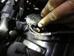
First he spliced in the harness to the back of the main ECU connection plug:
![]()
The other end of the harness (which stays with the bike) gets plugged into the log box which is attached to the lap top with the Woolich tuning software for the EX400 downloaded onto it.
![]()
We had a look at the softwares features and could see that there was no facility for disabling the decel fuel shut off (what causes the jerkiness on/off the throttle around town).
We were able to disable the gear position sensor and the purge valve which cleared error codes 25 and 3A respectively. There was no facility for disabling the Air switching (PAIR) valve though and I still have error code 64 showing plus the CEL is still on.
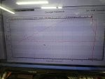
We did a dyno run and you will see from the graph below by looking at the horizontal dotted optimum Air/Fuel ratio line (13:1) that the bike is very lean at 3.5K rpm - 5Krpm then runs a little rich till about 9Krpm then its pretty much bang on till redline. I knew it was lean down low as it farts around town at low revs on a light throttle.
![]()
So we did a run using the auto tune function which is part of the Woolich software package. It calculated a new fuel map to correct the lean and rich parts of the existing map but unfortunately he could not get it to apply despite trying multiple times.
We couldn't ring the Woolich guys in Australia as they dont have telephone support, only e-mail. I'm told this is so they dont get hassled all day with calls. By this stage it was 3.30pm and my mate was keen to get a dyno run in with his bike so we flagged it.
So it will be interesting to hear from Woolich what they think the issue was. It wouldn't be so frustrating if the tuner was nearby but it's a 1100km round trip to go back. :frown:
I had an unsuccessful attempt last week at a Dyno tuners.
This is how it played out.
First he spliced in the harness to the back of the main ECU connection plug:
The other end of the harness (which stays with the bike) gets plugged into the log box which is attached to the lap top with the Woolich tuning software for the EX400 downloaded onto it.

We had a look at the softwares features and could see that there was no facility for disabling the decel fuel shut off (what causes the jerkiness on/off the throttle around town).
We were able to disable the gear position sensor and the purge valve which cleared error codes 25 and 3A respectively. There was no facility for disabling the Air switching (PAIR) valve though and I still have error code 64 showing plus the CEL is still on.
We did a dyno run and you will see from the graph below by looking at the horizontal dotted optimum Air/Fuel ratio line (13:1) that the bike is very lean at 3.5K rpm - 5Krpm then runs a little rich till about 9Krpm then its pretty much bang on till redline. I knew it was lean down low as it farts around town at low revs on a light throttle.
So we did a run using the auto tune function which is part of the Woolich software package. It calculated a new fuel map to correct the lean and rich parts of the existing map but unfortunately he could not get it to apply despite trying multiple times.
We couldn't ring the Woolich guys in Australia as they dont have telephone support, only e-mail. I'm told this is so they dont get hassled all day with calls. By this stage it was 3.30pm and my mate was keen to get a dyno run in with his bike so we flagged it.
So it will be interesting to hear from Woolich what they think the issue was. It wouldn't be so frustrating if the tuner was nearby but it's a 1100km round trip to go back. :frown:
")


